





In the high-stakes world of medical, analytical, and industrial laser systems, the fiber laser probe is often the most critical point of failure. While engineers frequently focus on the laser source or the delivery fiber itself, the connector—the mechanical and optical bridge between components—is increasingly recognized as the linchpin of system reliability. Selecting the right connector is no longer a peripheral procurement task; it is a fundamental system-level design decision that dictates the operational success, thermal management, and long-term viability of the entire assembly.
The optimal connector is rarely the one boasting the highest isolated laboratory specification. Instead, it is the one that provides the most stable optical performance, the most manageable thermal footprint, and the highest level of practical serviceability under the harsh, often unpredictable realities of field deployment.
The Strategic Importance of Connector Selection
In a fiber laser probe, a connector acts as more than a simple mechanical interface; it is a critical component that governs optical loss, back reflection, and contamination risk. As laser systems push toward higher average power, increased peak power, and more demanding coupling precision, the margin for error at the interface shrinks.
A connector that introduces even marginal alignment instability or modest optical loss acts as a thermal bottleneck. In compact probe designs, where heat dissipation is already a significant challenge, this localized energy loss can degrade components, reduce output consistency, and ultimately shorten the service life of the entire probe. Consequently, connector selection must be treated as a primary engineering discipline, transcending simple component comparison to become a core element of probe-level architecture.
Optical Performance: The Physics of Loss and Reliability
The engineering team’s first priority is invariably optical performance, encompassing insertion loss (IL), return loss, and physical alignment. These factors are not merely academic—they dictate the beam quality and thermal stability of the system.
The Mathematics of Thermal Loading
Insertion loss is the most tangible metric of a connector’s efficiency. The power output ($Pout$) from an interface is defined by the input power ($Pin$) and the insertion loss ($IL$) as follows:
$$Pout = Pin times 10^(-IL/10)$$
The resulting power loss ($P_loss$) is:
$$Ploss = Pin – Pout = Pin times (1 – 10^(-IL/10))$$
Consider a real-world scenario: a 100 W laser coupled through a connector with an insertion loss of 0.5 dB. In this instance, the connector-related loss reaches approximately 10.9 W. In many short-fiber probe assemblies, the intrinsic fiber attenuation is negligible compared to this interface loss. Consequently, the connector becomes the primary heat source. If that 10.9 W is not effectively managed, the localized thermal stress can lead to catastrophic failure of the cladding, epoxy, or mechanical housing.
Variables in Alignment and Geometry
The consistency of this interface is affected by several critical design and manufacturing variables:
- Concentricity and Ferrule Tolerance: Micro-deviations in the fiber core alignment can lead to significant coupling losses.
- Surface Finish: The polish quality of the fiber end face determines the laser damage threshold, especially in high-peak-power systems.
- Mechanical Mating Force: Insufficient pressure can lead to air gaps, while excessive pressure can deform the ferrule, inducing stress-related birefringence or physical damage.
When these variables are not strictly controlled, the result is not just reduced efficiency, but increased back reflection, which can travel upstream and destabilize the laser source itself.
Chronology of Design: From Concept to Field Deployment
The integration of a connector follows a rigorous lifecycle, moving from laboratory optimization to the ruggedness of real-world use.
- Phase I: Requirements Definition: Teams must first categorize the operating environment—is it a cleanroom laboratory setting or a dusty, high-vibration industrial floor?
- Phase II: Prototype Selection: Engineers evaluate standard versus proprietary connectors based on power density requirements and fiber geometry.
- Phase III: Thermal and Optical Validation: Using high-speed thermal imaging and power meters, teams verify the behavior of the interface under sustained load.
- Phase IV: Life-Cycle Stress Testing: Probes are subjected to repeated mating cycles, vibration, and shock to simulate the expected service life.
- Phase V: Deployment and Maintenance Protocol: The development of cleaning and inspection procedures tailored to the specific connector geometry.
Real-World Operating Conditions: Beyond the Spec Sheet
A connector that excels in a controlled, vibration-free laboratory environment may prove disastrous in the field. Engineering teams must rigorously account for the "human factor" and the physical environment.
Environmental Stressors
- Thermal Cycling: Rapid changes in temperature can cause differential thermal expansion between the fiber, ferrule, and housing, leading to alignment drift.
- Mechanical Shock and Vibration: In portable or handheld medical devices, the connector must maintain optical alignment despite accidental drops or constant movement.
- Contamination Susceptibility: In industrial environments, airborne particulates or oils can settle on the interface. If the connector design makes it difficult to inspect or clean, the system will eventually fail due to localized heating at the site of the contaminant.
Contamination Control and Serviceability
In both high-power industrial laser welding and precision medical laser surgery, contamination is the enemy of reliability. When a laser pulse hits a particle on an optical interface, the particle absorbs the energy, vaporizes, and often creates a crater in the fiber face.
The ideal connector architecture is one that facilitates easy inspection and maintenance. If the optical interface is buried deep within an inaccessible housing, even a trained technician may struggle to clean it effectively. In contrast, modular designs that allow for easy access to the ferrule face, or connectors with built-in protective shutters, significantly increase the MTBF (Mean Time Between Failures).
Manufacturability and Lifecycle Risk
A brilliant design that is impossible to manufacture at scale is a failed project. Connector selection must be balanced against the realities of the supply chain and production.
- Scalability: Does the connector require manual alignment by a master technician, or can it be assembled using repeatable, automated processes?
- Sourcing Risk: Proprietary or "boutique" connectors may offer slight performance advantages but introduce significant supply chain risk. If a sole-source manufacturer faces delays, the entire product line stalls.
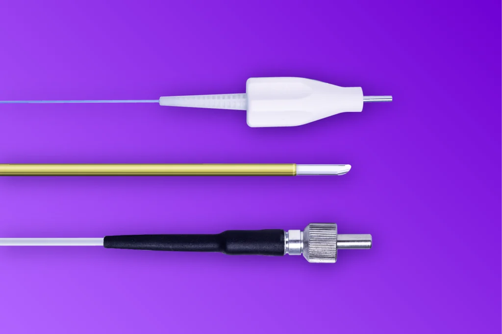
- Qualification Complexity: Standardized connectors (such as industry-recognized SMA or FC/PC variants) have established, well-understood failure modes and validation criteria. Using these often reduces the burden of regulatory and quality documentation.
Implications for Future Design
The trend toward more compact, high-power fiber laser probes suggests that the connector will remain the most critical variable in system reliability. We are seeing a shift toward "intelligent" connectors—interfaces that incorporate diagnostic sensors to monitor temperature and back-reflection levels in real-time.
As we look toward the future of laser-based manufacturing and medicine, the "connector-as-a-component" mindset is rapidly being replaced by "connector-as-a-system-solution." Engineers who treat the interface with the same level of design rigor as the laser resonator itself will define the next generation of reliable, efficient, and robust optical systems.
Fiber Laser Probe Connector Selection Checklist
When evaluating a connector for a fiber laser probe, engineering teams should use this comprehensive checklist to ensure all bases are covered:
- Optical Requirements: Does the connector handle the maximum peak and average power without reaching the material damage threshold?
- Thermal Budget: Is the heat generated by the insertion loss manageable within the existing cooling architecture?
- Mechanical Stability: Does the mating mechanism maintain alignment under the expected vibration and shock profiles of the application?
- Serviceability: Can a field technician easily inspect and clean the fiber face without specialized optical alignment equipment?
- Environmental Resilience: Is the housing material resistant to the cleaning agents, sterilization processes, or atmospheric contaminants present in the operating environment?
- Supply Chain Robustness: Is the component readily available from multiple sources, or does it represent a potential single point of failure in the production cycle?
- Manufacturing Yield: Can the assembly process be standardized to ensure consistent insertion loss across thousands of units?
By systematically addressing these factors, designers can move away from reactive troubleshooting and toward proactive, high-reliability engineering. The connector is not just a point of contact; it is the heartbeat of the fiber laser probe.